
Quick Specifications
| Model | JK-PB2A16S-15P |
|---|---|
| Dimensions | 300 x 100 x 24 mm |
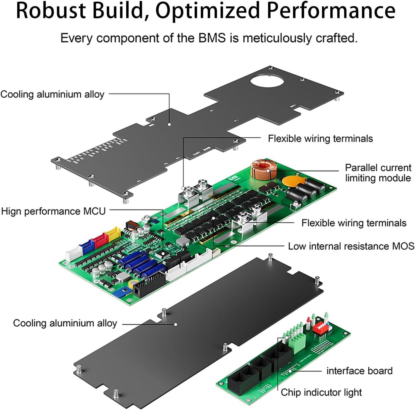
| Material | Aluminum Alloy Heat Sink & PCB |
| Balance | 2A Active Equalization (Energy Transfer) |
| Cont. Current | 150A |
| Peak Current | 300A |
| Strings | 7-16S (Ternary), 8-16S (LiFePO4), 14-16S (Lithium Titanate) |
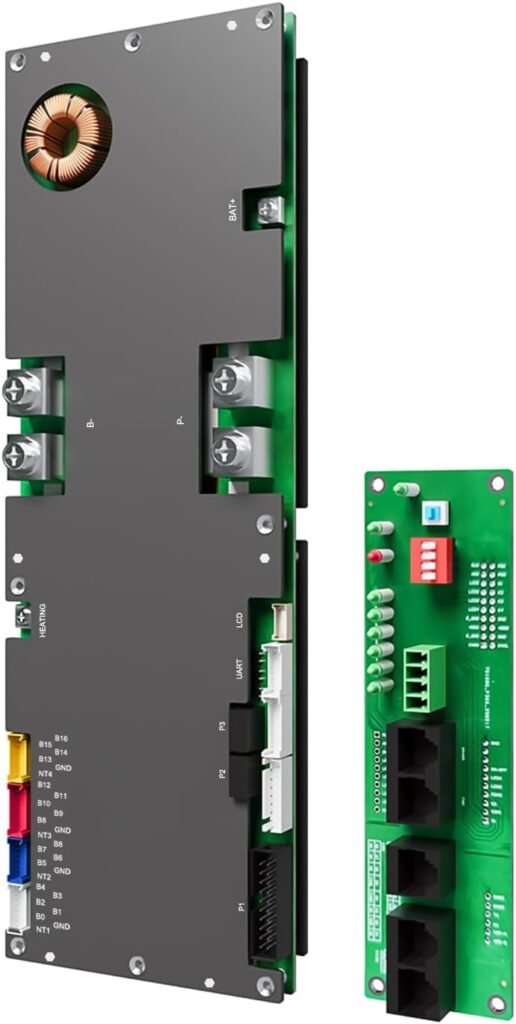
| Accessories | Interface Board (JK-CN-Link), Sampling Wires, Activation Switch, RJ45 Cable, Dry Contact Terminal, Heating Wire |
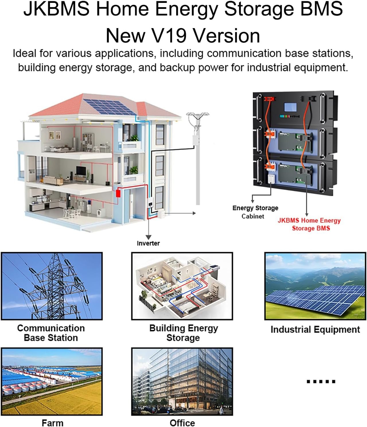
| Application Scenarios | High-power energy storage, Base station backup power, Solar power stations |
Product Video
Product Overview
The JK-PB2A16S-15P is a state-of-the-art intelligent protection board meticulously tailored for large-capacity series lithium battery packs in commercial and advanced residential energy storage systems. Engineered by Jikong Technology, this flagship Battery Management System (BMS) integrates high-precision voltage acquisition (±3mV), robust thermal management, and an exceptional 2A active balancing current.
Capable of handling a maximum continuous current of 150A and an impressive peak instantaneous current of 300A, the JK-PB2A16S-15P ensures reliable power delivery under heavy loads. With its incredibly low internal loop resistance of just 0.35 mΩ, it drastically minimizes heat generation during peak operation. Whether you are designing high-power energy storage arrays, base station backup power supplies, or off-grid solar power stations, this BMS provides the ultimate safety and efficiency for your lithium battery packs.
Core Energy Storage Features
The JK-PB2A16S-15P separates itself from standard consumer-grade BMS units through a suite of advanced, industrial-grade capabilities designed specifically for complex energy storage environments.
2A Active Equalization Technology
One of the most critical factors in extending battery lifespan is maintaining cell consistency. This BMS relies on proprietary energy transfer active balancing technology. Unlike passive balancers that burn off excess energy as heat, the JK-PB2A16S-15P transfers energy from high-voltage cells directly to low-voltage cells with a maximum continuous balance current of 2A. This ensures battery consistency to the greatest extent, improves battery range, and delays aging.
Advanced Parallel & Current Limiting Function
For users building massive energy storage banks, scalability is essential. The JK-PB2A16S-15P comes standard with a battery parallel current limiting function. When battery packs are connected in parallel, voltage differences can cause massive surge currents. When charging overcurrent occurs, the current limiting function activates, keeping the charging current constant at approximately 10A to fully protect the battery. This system supports connecting up to 16 BMS units in parallel.
Intelligent Communication (CAN & RS485)
Modern solar inverters and energy management systems require seamless data integration. The JK-PB2A16S-15P is equipped with CAN and dual RS485 communication interfaces.
-
CAN & RS485-1: Used for direct communication with major inverter brands (CAN default rate is 250K).
-
RS485-2: Dedicated to parallel battery pack connections and upper computer (PC) monitoring with a default baud rate of 115200.
Integrated Interface Board (JK-CN-Link)
To enhance user experience and installation convenience, this model includes the JK-CN-Link Interface Board as a standard accessory. This external board centralizes key controls, featuring an LED status indicator to judge BMS working status and remaining power, a reset button for troubleshooting, and a DIP switch for assigning communication addresses (from 0 to 15) in parallel environments.
Comprehensive Battery Protection Mechanisms
Safety is the cornerstone of the JK-PB2A16S-15P. The system monitors parameters in real-time and executes automated protections to prevent catastrophic failures.
Voltage & Current Safeguards
-
Overvoltage & Undervoltage Protection: Users can configure single-cell overcharge and undervoltage protection thresholds via the JIKONG BMS APP. The system shuts down charging or discharging if any string exceeds safe limits, recovering automatically once normal voltages are restored.
-
Overcurrent & Short Circuit Protection: Equipped with precise current acquisition, it triggers protection after a user-defined delay if the continuous discharge or charge current exceeds limits. Standard short circuit protection ensures absolute safety during wiring faults.
Thermal Management & Precharge
-
Extreme Temperature Protection: Features comprehensive charge/discharge over-temperature and low-temperature protection.
-
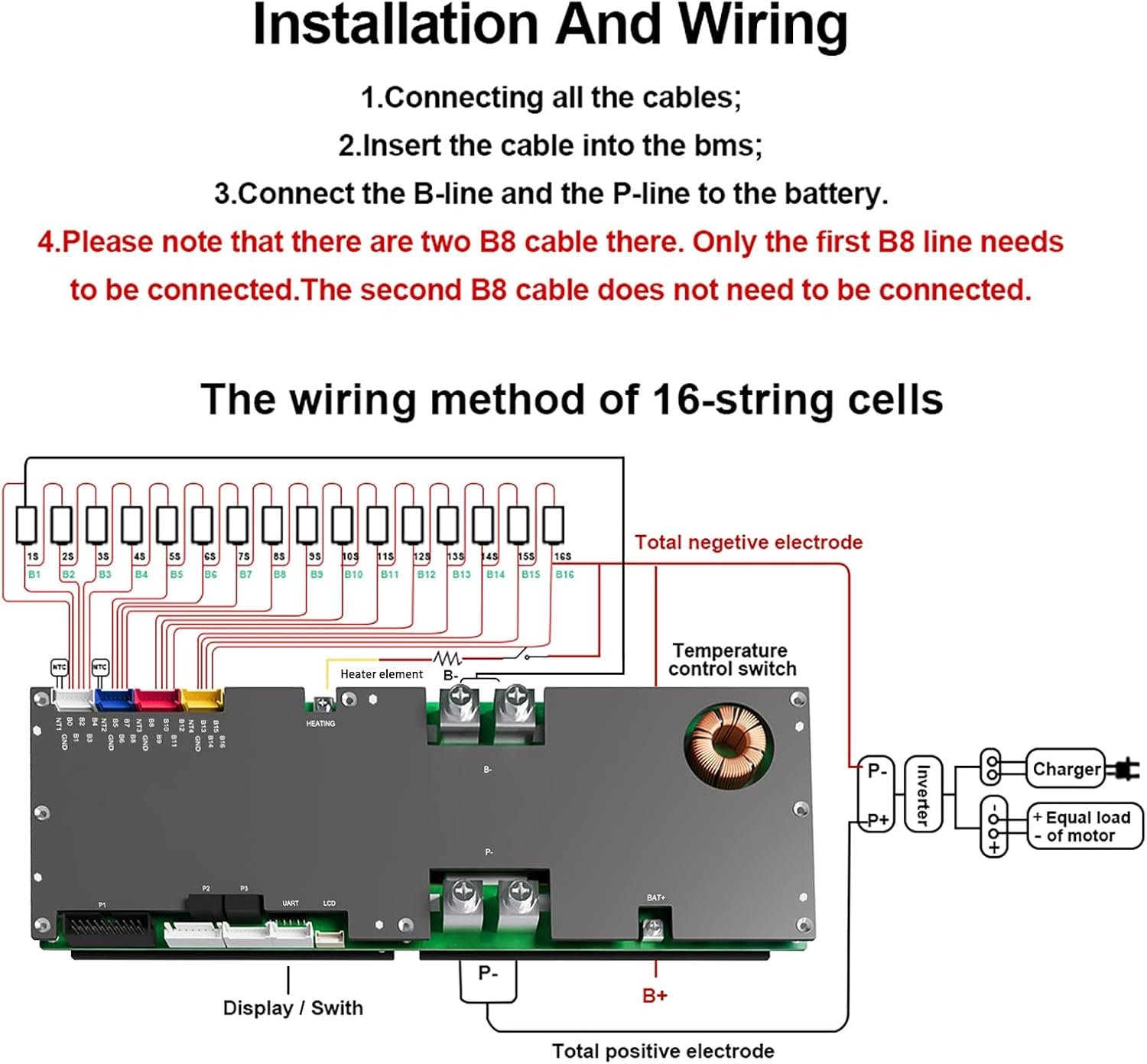
Heating Function: For freezing climates, it supports a dedicated heating function with a designed current of 10A. By connecting a resistance heater or heating film, the BMS warms the battery to restore cell activity before initiating a charge.
-
Discharge Precharge Function: The standard 5-second discharge precharge safely ramps up power to external loads, preventing high inrush currents from damaging sensitive inverter capacitors.
Programmable Dry Contacts & Emergency Switch
The board includes two standard dry contacts (COM1/S1 and COM2/S2). When the BMS detects an abnormal state (like over-temperature or over-charge), it can switch the dry contact status to drive an external alarm buzzer or activate a cooling fan. Additionally, an Emergency Switch function allows users to force a 30-minute charge/discharge window in critical situations, preventing total breakdowns.
Software & Remote Monitoring
Managing your energy storage system has never been easier thanks to robust software support across mobile and PC platforms.
Mobile App Integration (iOS & Android)
The built-in Bluetooth module allows seamless connectivity to the dedicated mobile APP. Through the app, users can:
-
View real-time battery status, accurate time logging, and precise capacity calculations (coulomb meter).
-
Modify essential working parameters such as trigger equalization differential pressure and overcurrent delays.
-
Control charge and discharge switches manually, or toggle the intelligent sleep function to save power during extended standby periods.
PC Host Computer Operations
For advanced configuration and parallel system monitoring, the JK-PB2A16S-15P connects to the Jikong host computer software via a USB to RS485 serial port cable. Facility managers can monitor all 16 parallel battery packs simultaneously through upper polling, ensuring total oversight of massive commercial storage banks.
Hardware Installation Guidelines
Physical Dimensions & Wiring
The main BMS board boasts a highly compact yet thermally efficient footprint of 300mm x 100mm x 24mm and weighs exactly 1000g. It utilizes robust M6 screws for the B- (Total negative battery) and P- (Load negative) terminals to handle high continuous currents without voltage drops.
DIP Switch Settings for Parallel Mode
When configuring multiple JK-PB2A16S-15P units in parallel, address assignment is required to prevent communication conflicts on the RS485 bus. The included interface board features a 4-pin DIP switch. Address 0 (all switches OFF) acts as the Host unit, while addresses 1 through 15 act as Slave units. Standard RJ45 Ethernet cables are used to daisy-chain the RS485-2 ports between the master and slave batteries.
Frequently Asked Questions (FAQ)
Q1: What battery chemistries are supported by the JK-PB2A16S-15P?
A: This highly versatile BMS supports 7 to 16 strings of Ternary Lithium batteries, 8 to 16 strings of Lithium Iron Phosphate (LiFePO4) batteries, and 14 to 16 strings of Lithium Titanate (LTO) batteries.
Q2: How does the parallel current limiting function work?
A: When connecting massive battery packs in parallel, varying pack voltages can cause a sudden rush of current. The JK-PB2A16S-15P automatically detects this and activates its current limiting module, restricting the cross-charging current to a safe 10A until the packs equalize.
Q3: Does this BMS support low-temperature charging environments?
A: Yes. The BMS has built-in low-temperature protection to halt charging when it is too cold. Furthermore, it supports an external heating module (max 10A current) that warms the battery pack up to a safe threshold before allowing the charge cycle to begin.
Q4: How is the BMS activated initially?
A: The board has no direct power-on switch on the main unit and uses a charging activation mode; applying a charger voltage 2V higher than the battery voltage will wake it up. Alternatively, users can utilize the included Activation Switch accessory or the Interface Board reset button for immediate activation.